Navigation: WireCAD Specific CAD Functions > WireCAD Equipment Library Functions > Advanced Library Functions >
Custom Shape Files


|
Navigation: WireCAD Specific CAD Functions > WireCAD Equipment Library Functions > Advanced Library Functions > Custom Shape Files |
|
|
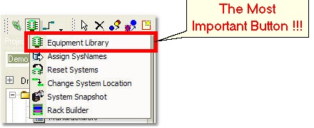
Using Custom Shape Files ![]()
Menu: Tools>Equipment>Equipment Library [Display Preferences]
Default keyboard shortcut: LE
Function:
Allows you to apply an equipment definition to a custom shape file.
Shape files are dwg files that have been place in the %BLOCKS%\Shape Files\ folder. There are two modes in which shape files work:
Basic Shape File Mode
Here we simply apply WireCAD ports to an existing dwg file. It can be any file in plan view mode. In this mode WireCAD will apply equipment definitions to dwg files. This function uses the Display Properties to determine the pin spacing, block width, etc. Whether the dwg file is fit or stretched to the display properties depends on the setting:
Item |
Description |
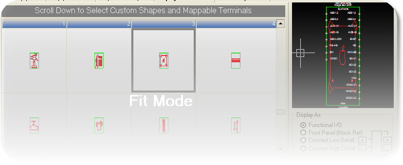
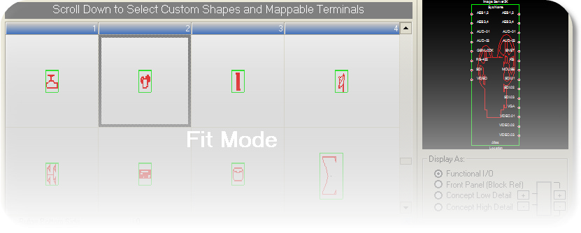
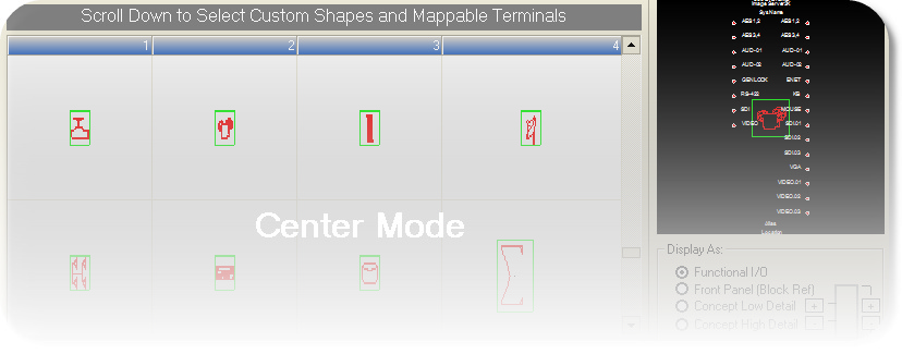
Shape Stretch Mode combo |
Fit/Center Fit scales the dwg into the Drawing Properties settings like Body Width, and (Pin Spacing x Pin Count). Center leaves the drawing size alone and simply applies ports. |
Examples:
Advanced Shape File Mode
In this mode we use dwg files and apply tags to items in the file to control their behaviour as we add ports to the file. We use the Shape File Editor to add these tags. To use the shape file editor Ctrl-Double-Click the in the the grid:
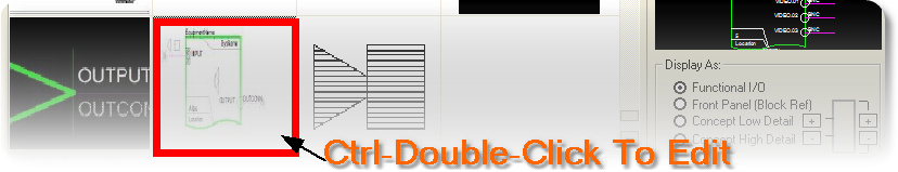
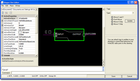
This launches the editor:
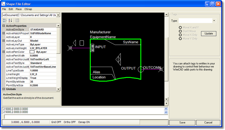
The editor allows you to place specific point to define where inputs and outputs are placed as well as tag items to control their behavior. Bear in mind that this editor is not meant to be a full CAD editor, but rather a Tag editor. If you need more control over the drawing use WireCAD to edit it, then open the file in the Shape File Editor and add the necessary tags.
Menu Structure
Item |
Description |
File>Open |
Opens dwg files |
File>Save |
Saves the current file |
File>Save As |
Save the current file as |
File>Exit |
Close this |
Edit>Undo |
Undo the last action |
Edit>Redo |
Redo the Undone function |
Edit>Delete |
Delete the current selection set |
Place>Line |
Place a 2D Line segment by defining its end points |
Place>Circle |
Place a 2D Circle by defining its center point and radius |
Place>PolyLine |
Place a 2D polyline by defining vertices in the drawing space |
Place>Rectangle |
Place a rectangle by defining the lower left and upper right points |
Place>Connection Point Input (CP_IN) |
Place a connection point in the drawing. This will be repeated for every item selected in the Inputs list in the Equipment Library. Be sure to place on an OSnap point. |
Place>Connection Point Output (CP_OUT) |
Place a connection point in the drawing. This will be repeated for every item selected in the Outputs list in the Equipment Library. Be sure to place on an OSnap point. |
Place>SysName |
Place a SysName element. If you do not place a SysName element one will be added base on the Block Descriptors Map |
Place>Alias |
Place a system Alias element. If you do not place a system Alias element one will be added base on the Block Descriptors Map |
Place>Location |
Place a system Location element. If you do not place a system Location element one will be added base on the Block Descriptors Map |
Osnap |
Sets Object Snap Points |
Tag Type
You add tags to items within the drawing by selecting the item and then assigning a Tag Value from the dropdown 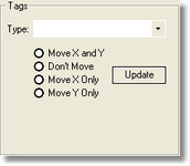 Select a Type and a behavior.
Notes: You must use Polylines for the body.
You must have either a CP_IN, CP_OUT, or both.
Item |
Description |
BODY |
Tag a Polyline that describes the body of the functional block |
NON_REPEATING_ELEMENT |
Tag static elements that do not repeat. You can then assign behaviors that determine movement as the block grows or shrinks. |
REPEATING_ELEMENT_INPUT |
Tag elements that repeat once for every input that is selected in the Inputs list of the Equipment Library. |
REPEATING_ELEMENT_OUTPUT |
Tag elements that repeat once for every output that is selected in the Outputs list of the Equipment Library. |
CP_IN |
Tag a Point entity that represents the point to which we will attach wires. Automatically attached when you use the Place>Connection Point Input (CP_IN) function. |
CP_OUT |
Tag a Point entity that represents the point to which we will attach wires. Automatically attached when you use the Place>Connection Point Output (CP_OUT) function. |
Tag Behavior
Item |
Description |
Move X and Y |
Tagged item moves in the X and Y direction as the size of the body changes with the addition of ports. |
Don't Move |
Don't move this item. |
Move X Only |
Tagged item moves in the X direction as the size of the body changes with the addition of ports. |
Move Y Only |
Tagged item moves in the Y direction as the size of the body changes with the addition of ports. |
Examples
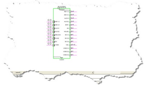
The Shape File to the right has a rotated INCONN text entity, some repeating elements on both the Input and Output side and some static elements that move in the X and Y directions as the block is scaled. Inherits:
Note: SysName, Alias and Location are missing from this shape file so WireCAD will place them based on the Block Descriptor Locations See the results below: |
|
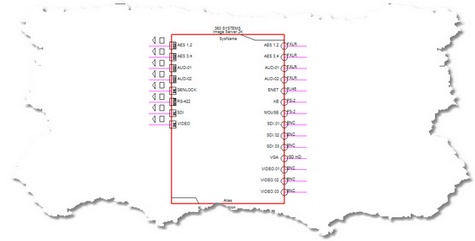
Looks like this: |
|
Or this, depending on your Display Properties settings |
|