Navigation: WireCAD Specific CAD Functions > WireCAD Equipment Library Functions >
Overview


|
Navigation: WireCAD Specific CAD Functions > WireCAD Equipment Library Functions > Overview |
|
|
Equipment Library Overview ![]()
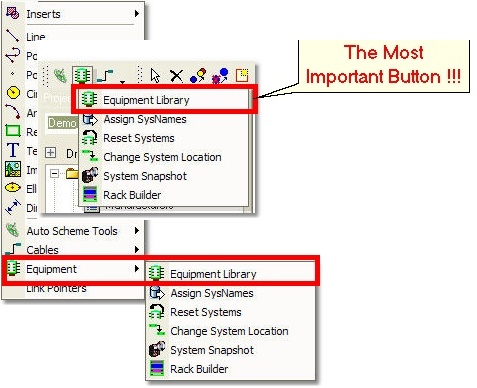
Menu: Tools>Equipment>Equipment Library (Active Drawing)
Default keyboard shortcut: LE
Function:
Note: You need an active drawing to access the Equipment Library
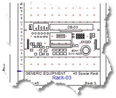
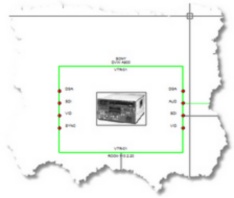
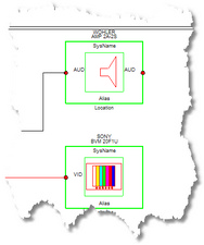
WireCAD uses a database of equipment definitions to create functional block diagrams and rack layouts:
Find Equipment Tab
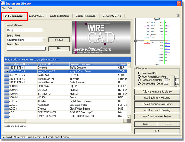
Equipment Library Control Descriptions
Item |
Description |
Industry Sectors combo |
Search by Industry Sector. |
Search Field combo |
Select the field to search on. |
Search Text textbox |
Enter the data to search for in the field selected by the Search Field. |
<Find All> |
Query the entire database. |
<Find> |
Query for the search criteria. |
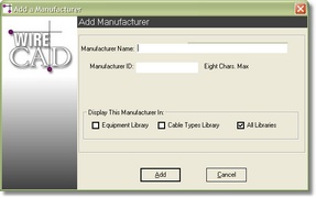
<Add Manufacturer to Library> |
Launches New Manufacturer dialog:
For more information see Adding Manufacturers to the database. |
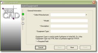
<Add Equipment to Library> |
Launches New Manufacturer dialog:
For more information see Adding Equipment to the database. |
<Delete Equipment from Library> |
Delete the selected equipment and all of its I/O from the database. |
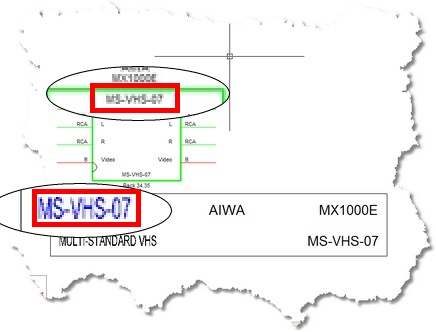
<Add This Item to Drawing> |
Create this item as it appears in the Preview window in the drawing. |
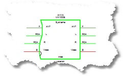
<Add This System to Project> |
Create an entry in the Project Systems database. |
<View Mechanical> alternately <View I/O> |
Toggles between the Mechanical view and the I/O view.
|
<Exit> |
Hide the library. |
Find Grid Functions |
|
Copy Equipment |
Hold the Alt key while dragging and dropping one record to another. You will be prompted to copy the I/O and the equipment data. |
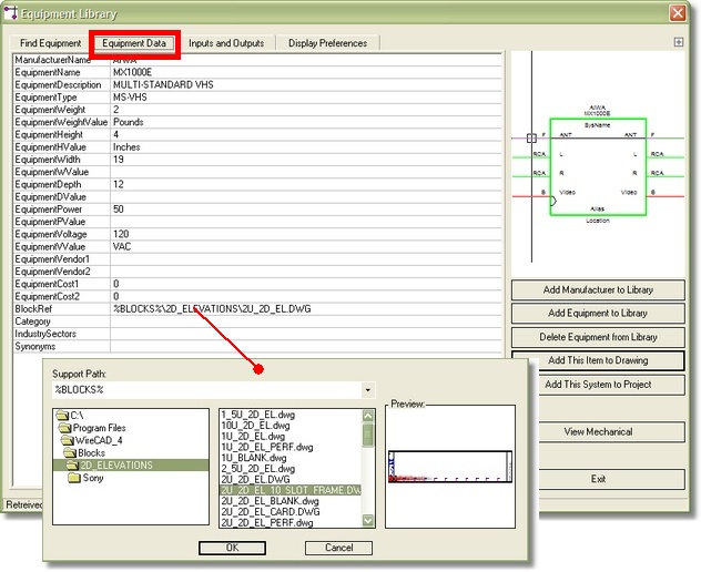
Equipment Data Tab
Equipment Library Field Descriptions
Field Name |
Description |
Manufacturer Name |
The Manufacturer Name |
Equipment Name |
The Model Name or Number |
Equipment Description |
Description |
Equipment Type |
SysName Prefix Field. All SysNames will use this value and a numeric value to create the SysName:
|
Equipment Weight |
Weight Quantity |
Equipment Weight Value |
Weight Value. i.e. pounds, kilos, etc. |
Equipment Height |
Height Quantity |
Equipment H Value |
Height Value. i.e. Rack Units, Inches, Centimeters. |
Equipment Width |
Width Quantity |
Equipment W Value |
Width Value. i.e. Inches, Centimeters. |
Equipment Depth |
Depth Quantity |
Equipment D Value |
Depth Value. i.e. Inches, Centimeters. |
Equipment Power |
Power Consumption Quantity |
Equipment P Value |
Power Consumption Value. i.e. Watts, VA, KVA |
Equipment Voltage |
Voltage Quantity |
Equipment V Value |
Voltage Value. i.e. AC, DC |
Vendor 1 , 2 |
Vendor Name |
Cost 1 , 2 |
Cost associated with vendor 1 and 2 |
BlockRef |
External CAD Block Reference. For use the View Mechanical function to create rack layouts:
Click <View Mechanical> to view. |
Image |
External Image File Reference. Future. |
Category |
Categorical search field. |
IndustrySectors |
Industry sectors that this equipment touches. |
Synonyms |
Synonym search field. |
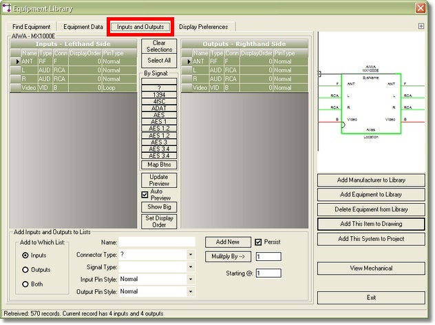
Inputs and Outputs Tab
Inputs and Outputs Control Descriptions
Item |
Description |
||||||||||||||||
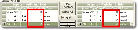
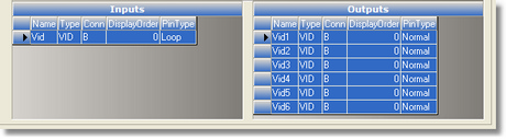
Inputs grid |
Copy from one grid to the other by dragging and dropping while holding the Alt key. Reorder the record set by dragging the record selector:
|
||||||||||||||||
Outputs grid |
Copy from one grid to the other by dragging and dropping while holding the Alt key. Reorder the record set by dragging the record selector:
|
||||||||||||||||
<Clear Selections> |
Clear the selection set and thereby all pins from the preview. |
||||||||||||||||
<Select All> |
Select all I/O from both lists. |
||||||||||||||||
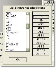
By Signal Buttons |
Provides a simple means to select all I/O of a given Signal Type. To map your own Signal Types to the 12 button set use <Map Btns>. |
||||||||||||||||
<Map Btns> |
See above.
|
||||||||||||||||
<Update Preview> |
Re query the database with the current I/0 and selection set and update the preview. |
||||||||||||||||
Auto Preview checkbox |
Automatically updates the preview after changes to the selection set. This can be annoying with particularly large devices that require several seconds to update. |
||||||||||||||||
<Show Big> |
Hides the Add Inputs and Outputs to Lists section in favor of large I/O lists. |
||||||||||||||||
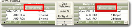
<Set Display Order> |
If you drag the record selector around and get the I/O to display the way you want and want to save the current configuration, click <Set Display Order> to add a numeric sequence from top to bottom to the DisplayOrder field. In order to return to your display order, you must resort by the DisplayOrder field. You can do this by clicking on the column header:
|
||||||||||||||||
Add Inputs and Outputs to Lists |
|||||||||||||||||
Add to Which List option |
Clicking <Add New> or <Multiply By -->> will add the current values to the selected option. Inputs: Adds to the Inputs list only. Outputs: Adds to the Outputs list only. Both: Adds to both the Inputs and Outputs list simultaneously. |
||||||||||||||||
Name |
The name of the port. |
||||||||||||||||
Connector Type combo |
The Connector of the port. Note: This field supports direct entry. Items added here will also be added to the Connectors database. |
||||||||||||||||
Signal Type combo |
The Signal Type of the port. Note: This field supports direct entry. Items added here will also be added to the Signal Types database. |
||||||||||||||||
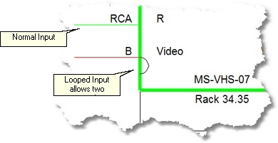
Input Pin Style combo |
Normal or Looped input:
|
||||||||||||||||
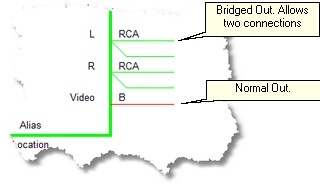
Output Pin Style combo |
Normal or Bridged output:
|
||||||||||||||||
<Add New> |
Add a single row based on the Add to Which List option |
||||||||||||||||
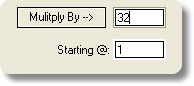
<Multiply By -->> button and textbox |
Add multiple rows based on the Add to Which List option, the Number of Rows entered and the Starting @ number.
Example: Let's say you want to add 32 video inputs and outputs to the selected equipment.
4. Enter 1 in the Starting @: field. This starts us counting at number 1. 5. Click <Multiply By -->> .
32 records will be added to each the Inputs and Outputs lists formatted as follows:
|
||||||||||||||||
Starting @: textbox |
See above. |
||||||||||||||||
Persist checkbox |
Retain the data in the Name, Connector, Signal Type, etc fields after an Add New or Add Multiple function. |
||||||||||||||||
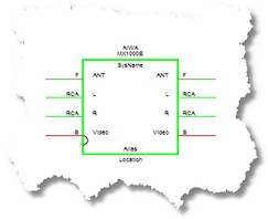
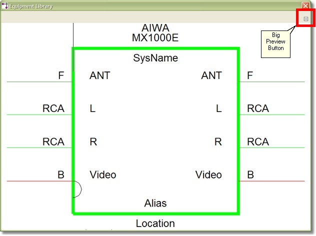
Enlarged Preview
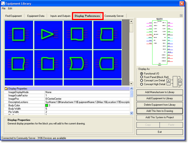
Display Properties Descriptions
Item |
Description |
Image Display Mode |
Sets whether or not an image or drawing icon is displayed in the Function IO block. |
Image Scale Factor |
Sets the scale factor of a displayed image or drawing icon. |
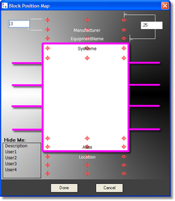
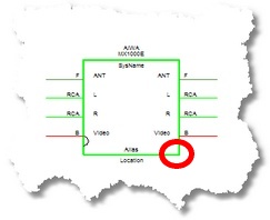
Image Position |
Sets the basepoint for the displayed image or drawing icon. |
Sets the location of the block descriptors (Sysname, Manufacturer Name, etc.).
|
|
Body Color |
Displays a standard color dialog to set the Body Color:
|
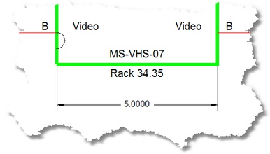
Body Width |
Sets the horizontal block dimension:
|
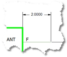
Pin Width |
|
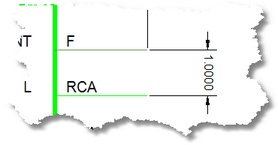
Pin Spacing |
|
Vertically Center |
Center the Pins in the block. |
Tear Left Side |
Dependant on Bulge Left Side. |
Tear Right Side |
Dependant on Bulge Right Side. |
Tear Top Side |
Dependant on Bulge Top Side. |
Tear Bottom Side |
Dependant on Bulge Bottom Side. |
Bulge Left Side |
Polyline bulge factor determines the size of the left side Tear. |
Bulge Right Side |
Polyline bulge factor determines the size of the right side Tear |
Bulge Top Side |
Polyline bulge factor determines the size of the top side Tear |
Bulge Bottom Side |
Polyline bulge factor determines the size of the bottom side Tear |
Text Height |
The height in DU of all text in the block |
Nudge Pin Text Vertical Position |
Vertical offset from default position. Usually used in conjunction with a Text Height change to properly align and position the text. |
Nudge Connector Vertical Position |
Vertical offset from default position. Usually used in conjunction with a Text Height change to properly align and position the text. |
Vertical Padding |
Sets the space between the inside of the block and the text. |
Block Reference (Read Only) |
Shows the fully qualified block reference path. |
Overview |
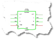
Used to determine which records from the Input and Outputs table to map onto a selected terminal. This has to do with terminals that have both an input and an output and which Inputs and Output match up and map onto a given terminal. Modes: |
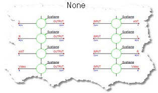
None: |
No matching attempted. Makes no attempt to match Inputs and Outputs and merge them to a single terminal.
|
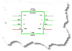
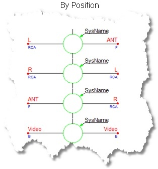
By Position |
Matches Inputs and Outputs by row in the record set and merges them together to a single terminal.
|
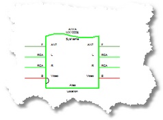
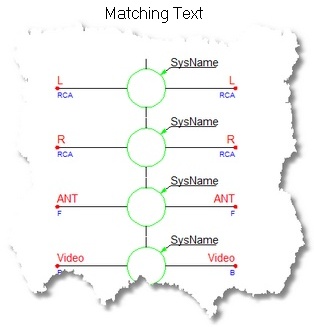
Matching Text |
Matches exact text records together and merges them together to a single terminal.
|
Standard Display Preference Shapes
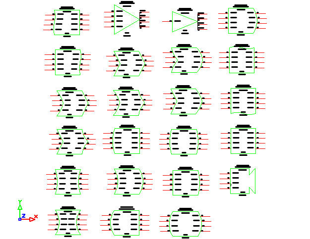
Overview:
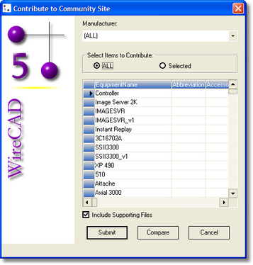
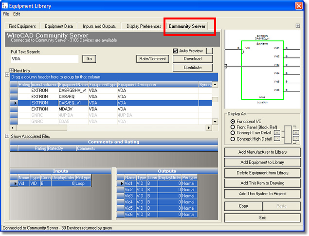
WireCAD maintains a community server that is accessible via the web. It is available for use by those with XLT or PRO versions of WireCAD. XL users can view but cannot contribute or download. If you are web connected and cannot see the community server it may be because of a proxy server or firewall setting. The Community Server needs access to port 3306.
Community Server Descriptions
Item |
Description |
Full Text Search textbox |
Full text search on the major fields of the community server. |
<Go> |
Launch the search. |
Rate/Comment |
Since this is entirely community based we need some way to let our peers know the state of a given definition. Use this button to rate or comment on the current item. Please be nice. |
Auto Preview |
Sets whether the preview window is automatically updated with the current selection. |
<Download> |
Downloads the current item to your local database. You will have the opportunity to change the signal types to match your local conventions. Also downloads any supporting documents like a front panel, image, icon, etc. |
<Contribute> |
Upload selected items to the Community Server.
|
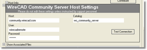
Host Info (Must click expando button to view) |
This is normally only edited if you are instructed to do so by WireCAD staff or if you have purchased the Internal Community Server. |
Inputs and Output grid |
Read only display of the inputs and outputs.
|
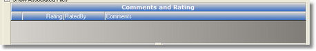
Comment grid |
Read only display of any comments associated with this device.
|
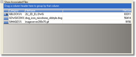
Associated Files grid (Must click expando button to view) |
Read only display of any associated files that have been uploaded with this device.
|