Navigation: WireCAD Specific CAD Functions > WireCAD Equipment Library Functions > Basic Library Functions >
Adding Functional Equipment Blocks to Drawing


|
Navigation: WireCAD Specific CAD Functions > WireCAD Equipment Library Functions > Basic Library Functions > Adding Functional Equipment Blocks to Drawing |
|
|
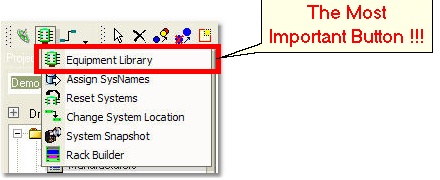
Adding Functional Blocks ![]()
Menu: Tools>Equipment>Equipment Library ~ Inputs and Outputs Tab
Default keyboard shortcut: LE
Function:
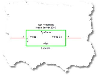
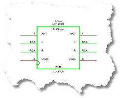
Add a functional block diagram of the selected equipment to the current drawing. The functional block diagram inherits global attributes, such as the pin color by Signal Type. WireCAD allows you the ability to determine which Inputs and Outputs to display upon block creation.
Note: Once a block is created, it cannot be edited. To change any of its display parameters (other than Text Style formatting and visibility), you must create another version of the block and insert it in place of the existing one.
How To: Add a Functional Block to a Drawing.
Assumes that you have already added the Manufacturer, Equipment and Inputs and Outputs.
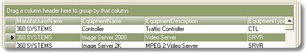
1. From the Find tab, select the desired equipment. |
|
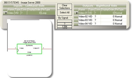
2. Switch to the Inputs and Outputs tab |
|
3. Select the Inputs and Outputs to display. Start by clicking <Clear Selections>, then select individual records by clicking on their Record Selectors.
You can select a range of records by holding the <Shift> key and select groups of records by holding the <Ctrl> key while clicking on the record selector.
Alternately, you can select all I/O related to a Signal Type by selecting one of the By Signal buttons.
Note: If you wish to display all Inputs and Outputs, skip steps 2 and 3. |
|
4. Edit the Display Preferences |
|
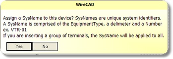
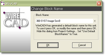
5. Click <Add This Item to Drawing>. What happens next depends on the Use Default Block Names setting. If False, you will be given a chance to name the block, otherwise WireCAD will name it for you. Note. The Equipment as it is currently displayed will be added to the Blocks table of the drawing file and you will be able to place an Insert of the block in the Active Drawing space. |
For more on Assigning SysNames see here.
Use Default Block Names = False:
|
6. Done. |
|
|
After completing this command, be sure to add Inputs and Outputs and complete the BlockRef Field. |