Databases > Cables
Commandline: cg
Explanation
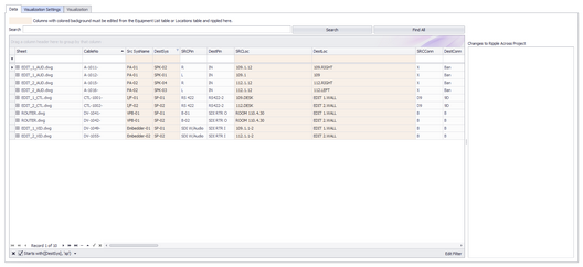
This is the main Cables table view. You can print, export and edit this view. Some fields are marked read only because they inherit their data from other tables. Changes to those fields should be done in the other tables then rippled into this table.
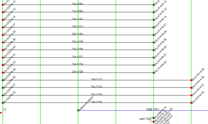
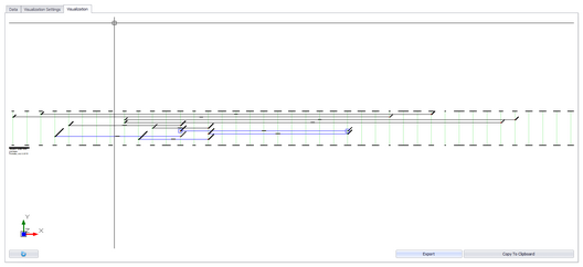
This grid contains a Visualizer that lets you see the data in graphical form. The Visualizer associated with this grid will create a Ladder diagram of the selected cables.

Prerequisites
Cable numbers assigned in a drawing.
Related Topics
Data Tab Options
Item |
Description |
Search |
Search the collection for the search term. |
Find All |
Clear the search field and return all records. |
Ripple List |
Changes you have made that may need to be rippled across the drawing set. The ripple will occur after you save the grid to the database. Note: you do not need to ripple changes that do not appear in a drawing. For example if you change the Cable Type Manu and Cable Type fields, neither of those fields have a corresponding display in a drawing. So no ripple is required to keep the drawing in sync with the database. If you are unsure - ripple. |
|
|
Expert Mode |
Removes the read-only flags and puts the grid in a completely editable state. Not for beginners. |
Add Many |
Only available in Expert Mode this tool adds blank records to the table that you can edit as a spreadsheet. |
|
|
Tools |
|
Repair Equipment List |
Scans the Cables table for SysNames then compares with the Equipment List. Missing SysNames are then added to the Equipment List. |
Attach Document |
Any document can be attached to any record. This is useful for storing cut-sheet data, test data, and images. |
|
|

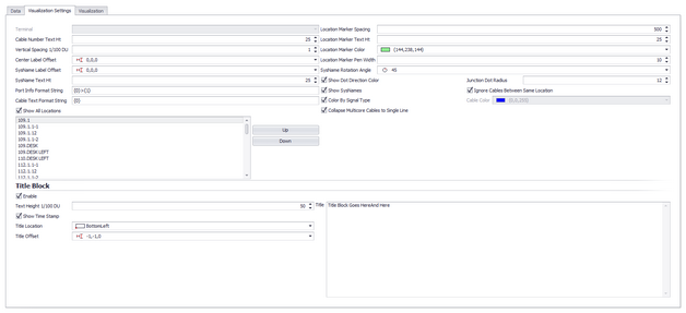
Visualization Tab Options
Item |
Description |
Terminal |
Not yet implemented. |
Cable Number Text Height |
The text height of the Cable Number element |
Vertical Spacing 1/100 DU |
How far apart vertically are the cables. |
Center Label Offset |
Where is the center label positioned with reference to the center of the polyline that represents the cable. |
SysName Label Offset |
Where is the SysName label positioned with reference to the end points of the polyline that represents the cable. |
SysName Text Hit |
The text height of the SysName label. |
Port Info Format String |
The following variables can be used along with the /n new line character to format the port info: {0}SysName {1}Port {2}Location {3}Alias {4}Connector {5}Cable Number {6}Cable Manufacturer {7}Cable Type
Example: Assume that the SysName is VTR-01. The PortName is VID-OUT and the Location is RK-10 The following Port Info Format string: {0}>{1}@{2} Will produce the result: VTR-01>VID-OUT@RK-10 |
Cable Text Format String |
The following variables can be used along with the /n new line character to format the Cable Text: {0}Cable Number {1}Cable Manufacturer {2}Cable Type {3}Length {4}Sheet |
Location Marker Spacing |
How far apart horizontally the vertical location markers are spaced. |
Location Marker Text Hit |
|
Location Marker Color |
|
Location Marker Pen Width |
|
SysName Rotation Angle |
|
Show Dot Direction Color |
Display a green dot on the source side and a red dot on the destination side of the cable. |
Show SysNames |
Show/Hide the SysName. |
Color By Signal Type |
Inherit cable color by Signal Type or set a single color for all cables. |
Collapse Multi-core Cables to Single Line |
Multi-core cables are represented by many records in the Cables table. You can choose to display a cable for each or collapse to a single cable. |
Title Block Enable |
Title Block stuff |
Text Height 1/100 DU |
|
Title Location |
|
Title Offset |
|
Title |

Data Tab Options
Item |
Description |
Export |
Export to file. |
Copy To Clipboard |
Copy to clipboard |
Refresh |
Refresh the preview. |