|
Drawing Cables |
  
|
|
Drawing Cables |
|
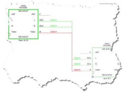
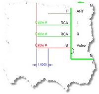
WireCAD provides a series of tools to draw cables. The only rule that this version of WireCAD imposes is that you must draw from one WireCAD device to another. You cannot draw a cable representing a spare that connects to nothing.
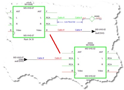
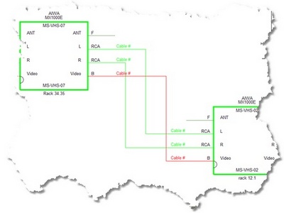
WireCAD provides a cable auto-routing tool that automatically routes the cable around other devices and, if selected, avoids other cables. The auto-router will always find a path for the cable, even if it means that the cable is drawn through another device or must overlay another cable. If you do not like the way a cable is routed, you have two choices; first: manually drawing the cable by selecting Manual Draw, second: select the cable and grab a grip on the cable and move it around.
|
If you manually draw cables or otherwise put them where you want them and them move a device, the auto-router will be invoked and re-route all your changes. |
Topics
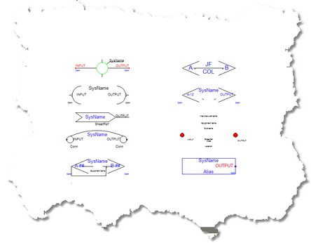
Devices have inputs and outputs, Cables have sources and destinations.
For purposes of this manual we will refer to Jacks, Junction Boxes, Router Crosspoints, Bulkhead connectors, and On-Sheet/Off-Sheet Pointers collectively as Terminals:
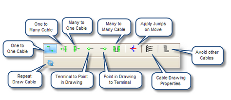
Draw Cables Control Descriptions
Item |
Description |
|
|
|
|
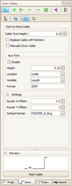
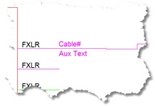
Cable Text Height |
The Cable# text entity height in DU. |
Replace Cable with Pointers checkbox |
Automatically draw Pointers instead of cables.
|
Draw every point in the cable. |
|
Avoid Other Cables checkbox |
Allows cables to overlay each other. True =
False =
|
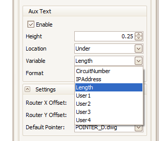
Enable the placement of Aux Text. |
|
Aux Text Height |
The height in DU of the Aux Text. |
Location |
The position of the Aux Text relative to the cable polyline. Over - positioned over the cable polyline. Under - positioned under the cable polyline. Bubble - Not yet supported.
|
Variable |
You may choose to populate the Aux Text with the following variables:
CircuitNumber - The Circuit Number as entered in the Cable Edit Dialog. IPAddreess - Not yet implemented. Length - The Length field as entered in the Cable Edit Dialog. User1 - The User1 as entered in the Cable Edit Dialog. User2 - The User2 as entered in the Cable Edit Dialog. User3 - The User3 as entered in the Cable Edit Dialog. User4 - The User4 as entered in the Cable Edit Dialog.
|
Format |
{0} represents the data from the selected variable. Example: the incoming data from the selected variable is 300 and you want to format it to represent meters to the reader. Your format field would be {0}m. The output would be formatted as 300m. |
Horizontal auto-router offset. When drawing cables, WireCAD uses an auto-routine algorithm. The X Offset determines how far away horizontally from other equipment and cables a new cable will rout.
|
|
Vertical auto-router offset. When drawing cables, WireCAD uses an auto-routine algorithm. The Y Offset determines how far away Vertically from other equipment and cables a new cable will rout.
|
|
Select the pointer to use when replacing cable with pointers |
|
Explanation |
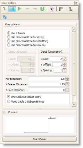
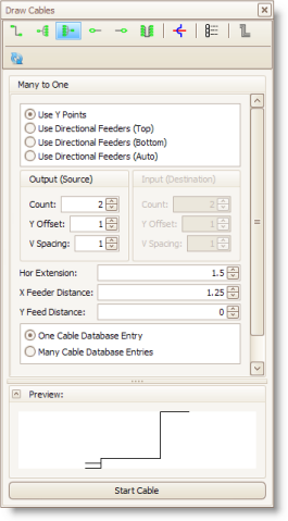
Used to indicate one output to many inputs |
|
|
|
|
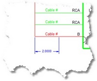
Count |
Destination count 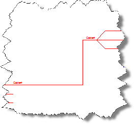 Count=3
|
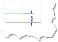
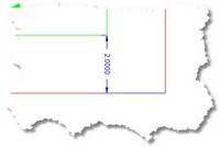
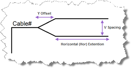
Y offset, Y Spacing, Hor Extension |
|
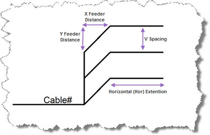
Feeder distances |
|
One Cable Database Entry |
Adds a single entry in the cables database and one Cable# text entity at the Y point. |
Many Cable Database Entries |
Adds a many entries in the cables database and many Cable# text entity at the connection points.
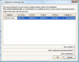
Note: One-to-Many and Many-to-One cables set to Many Cable Database Entries will assign the connection point closest to the cursor when the cable is double-clicked. The first assignment on the cable will enter the database as expected, subsequent assignments will display the Existing Ports dialog prompting you to decide how to number the cables.
|
Explanation |
Multiple outputs to one input |
|
|
Count |
Source count 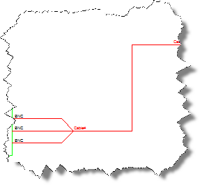 count=3 |
More information |
See above for a description of other settings |
Explanation |
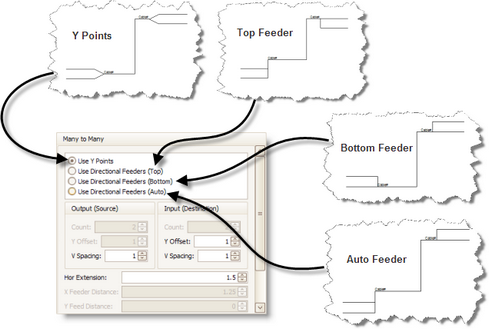
Many-to-Many cables behave like a buss. They are a collection of one-to-one cable drawn as a single polyline. When assigning cable numbers the connection point closest to the cursor is used.
See the above descriptions for more information about settings.
|
Count |
Source and destination count 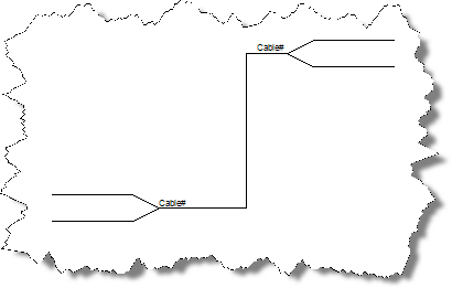 Count = 2 |
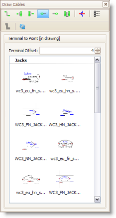
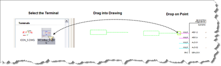
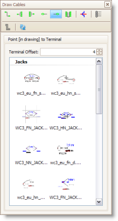
Displays the available Terminals sorted by Terminal style (Jack,Terminal, Pointer).
Note: Terminal file suffixes determine whether the file will be displayed in this window. Files having a _SD.DWG, or _S.DWG suffix will appear in this view. |
|
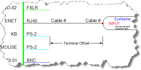
Terminal Offset |
Sets the distance between the connection point and the terminal basepoint
|
Displays the available Terminals sorted by Terminal style (Jack,Terminal, Pointer).
Note: Terminal file suffixes determine whether the file will be displayed in this window. Files having a _SD.DWG, or _D.DWG suffix will appear in this view. |
|
Terminal Offset |
see above |