Database > Equipment Library [I/O]
Drawing > Advanced Tools > Equipment Library [I/O]
Commandline: le
Several Others
Explanation
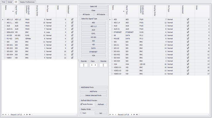
This is the Inputs and Outputs page. It represents the I/O of the currently selected device. Inputs are displayed in the left-hand grid and outputs are displayed in the right-hand grid. This is by convention only. You are free to place inputs on the right-hand side and vice versa. Each port record consists of a Name, Type, Connector and a Pin Type. Selected records will be included in the preview of any Function I/O and Concept blocks that you create.
I/O Tab Options
Item |
Description |
Inputs Grid |
The I/O grids. NOTE: Be sure to save your changes if you edit these grids manually by clicking File>Save. |
Outputs Grid |
|
|
|
Select All |
Manipulate the selection. |
Clear Selection |
|
All Inputs |
|
All Outputs |
|
Select by Signal Type |
Ten buttons in this frame will populate with the first ten signal types from the I/O records. Clicking the button will select all records in both grids of that signal type |
Reorder |
Move selection up/down. |
Copy |
Copy side-to-side. |
Add Ports |
|
Delete Ports |
Delete the selected ports. You will be prompted for each grid. No save is necessary |
Refresh |
Refresh the preview. |
Display Order |
Set and sort by the Display Order column. This allows you to rearrange the lists and be able to return later to your work. |