Database > Equipment Library [I/O] [Add Ports]
Drawing > Advanced Tools > Equipment Library [I/O] [Add Ports]
Commandline: le
Several Others
Explanation
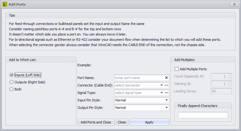
This is the Port Adder dialog. With it you add a single record, two records, or multiple records to the I/O grids. Here are some things to consider when naming your ports:
| 1. | For feed-through connections or bulkhead panels set the input and output Name the same. |
| 2. | Consider naming patchbay ports A-# and B-# for the top and bottom rows. |
| 3. | It doesn't matter which side you place a port on. You can always move it later. |
| 4. | For bi-directional signals such as Ethernet or RS-422 consider your document flow when determining the list to which you will add these ports. |
| 5. | When selecting the connector gender always consider that WireCAD needs the CABLE END of the connection, not the chassis side. |
Dialog Options
Item |
Description |
Add to Which List |
|
Port Name |
Enter the port name here. |
Connector (Cable End) |
From the global Connectors table. |
Signal Type |
From the global Signal Types table. |
Input Pin Style |
Straight pin (Normal) or looped (two connection points). |
Output Pin Style |
Straight pin (Normal) or bridged (two connection points). |
Add Multiples |
If checked a record will be created for each Count. The number will be appended to the Port Name info and formatted based on the Leading Zeros format. |
Finally Append Characters |
Useful if you want to add characters after the multiple count number has been appended. See the example below for more info. |
Examples
Example |
Result |
Add a single port to the Inputs table. |
|
Add a single port to the Inputs and Outputs list at the same time. |
|
Add 10 ports to each grid appending a port number to each record. |
|
Now let's create the 8 left line inputs of a stereo mixer. We will use the [Finally Append Characters] field to append the characters -LEFT after the number is created and appended to the Port Name. |
|