Drawing > PlanView and Layout Tools > Draw Backbone
Commandline: pwdc
Explanation
This tool allows you to draw a cable in Plan View space that is assigned to the Cables table.
Prerequisites
| 1. | SysNamed source and destination equipment placed in the Plan View space or: |
| 2. | Source and destination Location Boundaries placed in the Plan View space. |
Operation
This tool allows you to draw geometry in the Plan View space that represents the path of the cable. The process requires the following steps:
| 1. | Start the tool. |
| 2. | Select the source SysNamed equipment. |
| 3. | Select the destination SysNamed equipment. |
| 4. | Place the points in the polyline to finalize the appearance. |
Related Topics
Dialog Options
Item |
Description |
|---|---|
Cable Type |
|
Source Information |
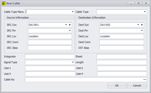
The source SysName is pulled from the drawing. You will need to selection the Src Pin and such. |
Destination Information |
The destination SysName is pulled from the drawing. You will need to selection the Dest Pin and such. |
Other Stuff |
|
Cable No |
Click the [...] button to generate a cable number. |