Drawing > PlanView and Layout Tools > Draw Backbone
Commandline: none
Explanation
Backbones are collections of cable/fiber that are contained in a single jacket that run from one location to another and are typically sized for growth. An example might be a fiber optic cable that contains 288 fiber cores that runs from building A to building B. We know that initially we will not use all 288 fibers and have planned for growth. As the facility needs change the usage of the backbone's fibers change.
WireCAD maintains backbones just like any multi-core cable with the exception that the Cables table record is flagged IsBackBone = true.
WireCAD will create a cable record for every core in the Cable Type used.
Prerequisites
| 1. | SysNames assigned to the panels/equipment to which you will attach the ends of the Backbone. |
| 2. | Multi-core Cable Type representative of the Backbone. |
Operation
This tool allows you to draw geometry in the Plan View space that represents the path of the Backbone. The process requires the following steps:
| 1. | Draw the polyline that represents the backbone. |
| 2. | If locations boundaries are found in the drawing the source and destination locations will be used. Otherwise you will be prompted to define a location for each end. |
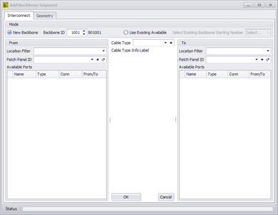
| 3. | Next you will be presented with the New Backbone tool where you will select the source and destination panels/ports and the cable type. |
| 4. | Clicking [OK] will build a record in the Cables table for each core in the multi-core cable type. |
| 5. | The polyline length populate the cable record Length field. |
Related Topics
Dialog Options
Item |
Description |
|---|---|
New Backbone |
Select whether we are creating a new number or assigning existing unused core. |
Backbone ID |
The number |
Use Existing Available |
|
Location Filter |
Filter the list by location |
From Panel Info |
Select the panel. The ports will be shown in the list. |
To Panel Info |
Select the panel. The ports will be shown in the list. |
Cable Type |
Select the Cable Type. |
|
|
|
|
|
|
|
Examples
Step |
Description |
|---|---|
|
|
Our drawing looks like this |
|
|
Step |
Description |
|---|---|
|
|
|
|
|
|
|
|
|