Application Menu > Settings
Commandline: set
Explanation
The Settings dialog is comprised of the following sections:
| • | Application - settings that determine the behaviour of WireCAD for this machine. |
| • | Basic |
| • | User - settings specific to your user profile on this machine. |
| • | Basic |
| • | Drawing |
| • | Project - settings specific to the current project. |
| • | Basic |
| • | Advanced |
NOTE: These are the stock basic settings panels. Third party developers may register their own settings panels. See their documentation.
Prerequisites
None
Related Topics
Dialog Options
Item |
Description |
|---|---|
Save |
Commit your changes and issue a SettingsChanged command to the application. |
Close |
Do nothing and discard your changes. |
Restore Defaults |
Restore the defaults of the current settings panel. |
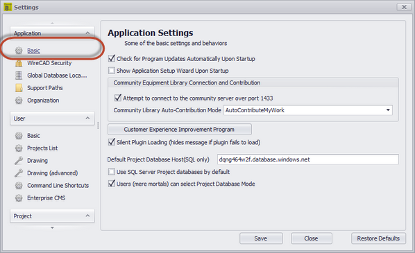
Application - Basic Panel Options
Item |
Description |
|---|---|
Check for Program Updates Automatically on Startup |
If updates are available you will see a banner pop up in the lower right-hand corner of the screen. |
Show Application Setup Wizard on Startup |
This is usually unchecked except the first run of the application. You can always start the Application Setup Wizard by clicking Application Menu > Application Setup Wizard. |
Community Server Contribution |
How will you contribute to the WireCAD Community? |
Customer Experience Improvement Program |
You must opt in to the CEIP. We will then gather usage and error data. The generic data will be uploaded to our servers and aggregated so we can bring you a better application. |
Silent Plugin Load |
Hide all error messages on startup. |
Default Project Database Host |
Applies only to SQL projects. Presets the New Project Wizard |
Use SQL Server Project Databases by Default |
Presets the New Project Wizard |
Users (mere mortals) can select Project Database Mode |
Some organizations may wish to limit selection of project database type. |
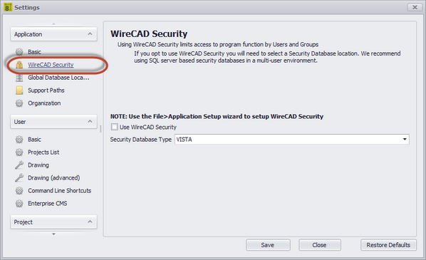
Application - WireCAD Security Panel Options
Item |
Description |
|---|---|
Use WireCAD Security |
Enable Security. When enabled the WireCAD security system uses the current login to determine program access. If your user is a member of the Administrators group you will be able to control the access of other users via the Application Menu > Security > Manage Security... dialog.
|
Database Type |
Typically you will only use security in a multi-user environment with a SQL host, but the capability exists to use file based VistaDB databases. |
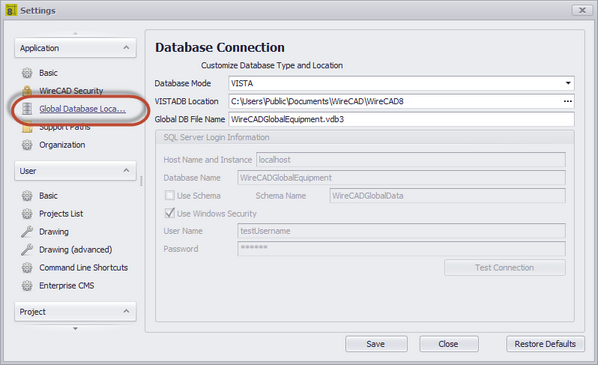
Application - Global Database Location Panel Options
Item |
Description |
|---|---|
Database Mode |
VISTA/SQL NOTE: SQL will work for SQL AZURE as well. We will need the database name and schema name. |
VISTADB Location |
Path to the VISTADB file that is your WireCADGlobalEquipment.vdb3 file. Note that this is the default name given to the global database file but you may change it. |
Global DB File Name |
|
SQL Server Login Info |
|
Host Name and Instance |
This can be a fully qualified path, ip address, or host name. |
Database Name |
The name of the global database to connect to. This is WireCADGlobalEquipment by default but you may choose to rename it. |
Use Schema |
WireCAD v8 supports multiple schema in the same database file. This is useful if you are using a cloud based SQL Server service that charges by the database. You can have a schema for your global database and one for each of your project databases. All contained within the same database file. |
Schema Name |
|
Use Window Security |
Use this if you wish Windows security to manage the login. This will not work with SQL Azure. |
User Name |
|
Password |
|
Test Connection |
Test to see if you can connect and have the appropriate privileges. |
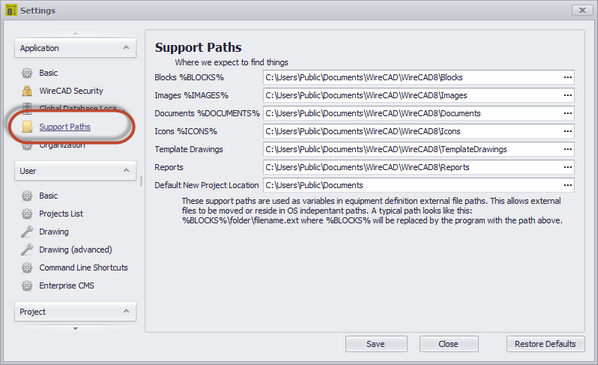
Application - Support Paths Panel Options
Item |
Description |
|---|---|
Block %BLOCKS% |
The path that will replace the %BLOCKS% variable in the equipment library. |
Images %IMAGES% |
The path that will replace the %IMAGES% variable in the equipment library. |
Documents %DOCUMENTS% |
The path that will replace the %DOCUMENTS% variable in the equipment library. |
Icons %ICONS% |
The path that will replace the %ICONS% variable in the equipment library. |
Template Drawings |
The path to the Template Drawings folder. This is the folder where Template Drawings are saved when using the File > Save As Template Drawing function is used and the folder that the New Drawing Wizard searches to fill the Templates list:
|
Reports |
The path to the top reports folder. This is a recursive search and will enumerate all subfolders and files. |
Default New Project Location |
Presets the New Project Wizard.
|
|
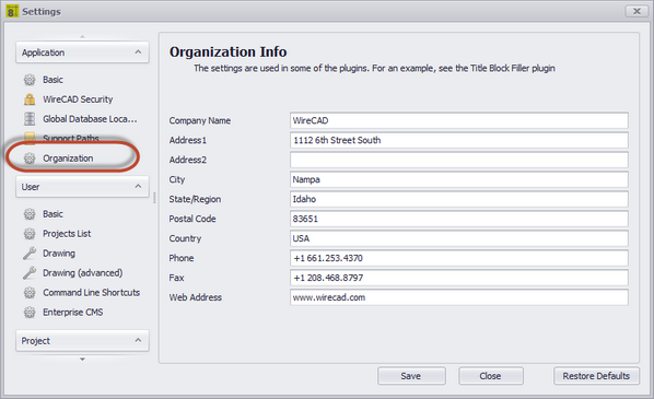
Application - Organization Panel Options
This one's self-explanatory
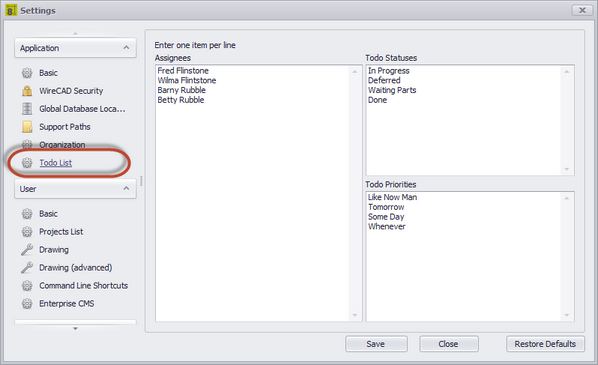
Explanation
Sets the dropdowns in the Project Todo List
Application - Todo Panel Options
Item |
Description |
|---|---|
Assignees |
List of people to whom a task may be assigned. |
Statuses |
List of todo item statuses. Modify this to suit your needs |
Priorities |
List of priorities. Again, make it fit your needs. |
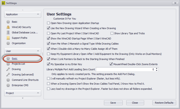
Item |
Description |
|---|---|
Open New Drawing Upon Application Startup |
Opens a blank new drawing when WireCAD starts. |
Use the New Drawing Wizard |
Shows the New Drawing Wizard when you click File > New. Allows the use of template drawings. If set to false, just creates a new drawing without a template. |
Open My Last Project When I Start WireCAD |
Behaves like earlier versions of WireCAD that opened the last project automatically on startup. |
Show Library Tips |
This shows the Tips and Tricks form in front of the Equipment Library. |
Show the WireCAD Startup Page |
The WireCAD Startup Page shows the latest news from the WireCAD ranch. |
Warn of Signal Type Mismatch |
When you finish drawing a cable WireCAD will check the source and destination port signal types and let you know if they don't match. You can use the new status panel to know the port type if you are confused.
|
When I Double-click a Many-to-Many Cable Assign All of Them. |
Many-to-Many cables that are set for Multiple Database Entries can either be assigned all at once by a single double-click, or if this setting is turned off a double-click will find the closest port to the cursor and assign that. |
Keep Equipment Library Open |
This is useful if you are using dual monitors and want to have the Equipment Library stay open on the other monitor. |
When I Link Pointers Go Back to the Starting Drawing When Finished |
The default Link Pointer function will leave you on the second sheet. If you set this to true it will jump you back to the first sheet. |
This is helpful when executing command line commands |
|
MouseWheel Double-click Zooms Extents |
|
Library Multiple Port Add Leading Zero Count |
|
I Will Manually Refresh the Project Explorer |
True to disable autorefresh on the Project Explorer. This may be helpful if your project grows to have hundreds of drawings. |
When a Drawing Opens Don't Show the Draw Cables Tool Panel |
|
Lazy Load my drawings in the Project Explorer |
True to disable recursive search of all drawing subfolders. This may be helpful if your project grows to have hundreds of drawings. |
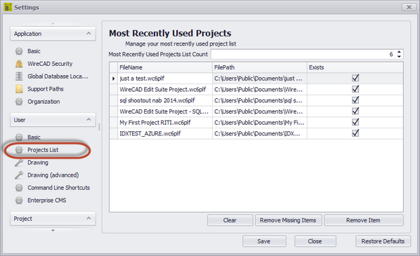
User - Projects List Panel Options
Item |
Description |
|---|---|
Most Recently Use Projects List Count |
How many items allowed in the list. |
Projects List |
|
Clear |
Reset the list. |
Remove Missing Items |
Remove items that cannot be found because the path has changed or is currently unavailable. |
Remove Item |
Remove the selected row. |
|
|
|
|
|
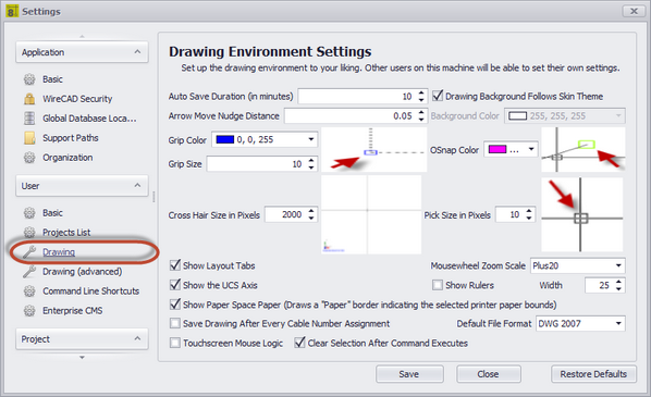
Item |
Description |
|---|---|
Auto Save Duration |
Sets the Auto Save Duration. Auto Save saves only drawings that are not currently involved in a function. |
Arrow Move Nudge Distance |
When nudging a selection how far do we move in the direction. |
Grip Color |
Sets the grip color. |
Grip Size |
Sets the grip size in pixels. |
Cross Hair Size |
Sets the cross hair size in pixels. |
Show Layout Tabs |
Shows the layout tabs at the bottom of the drawing frame |
Show UCS Axis |
Shows the UCS Axis:
|
Show Paper Space Paper |
When a layout is selected, show the current page size as returned by the selected printer as a white "page."
True
False |
Save Drawing After Every Cable Number Assignment |
Setting this to true is not recommended but will speed the assignment process. You are responsible then for saving the drawing to ensure drawing/database parity. |
Touchscreen Mouse Logic |
|
Clear Selection After Command Executes |
Overrides the default behaviour of leaving the selection set in tact after an operation. |
Drawing Background Follows Skin Theme |
|
Background Color |
Sets the background color. |
OSnap Color |
Sets the Object Snap Color. |
Pick Size |
Sets the pick size in pixels. The pick determines the search window when clicking the cursor. |
Mousewheel Zoom Scale |
How far do we zoom with every click of the mouse wheel |
Show Rulers |
|
Ruler Width |
In pixels |
Default File Save Format |
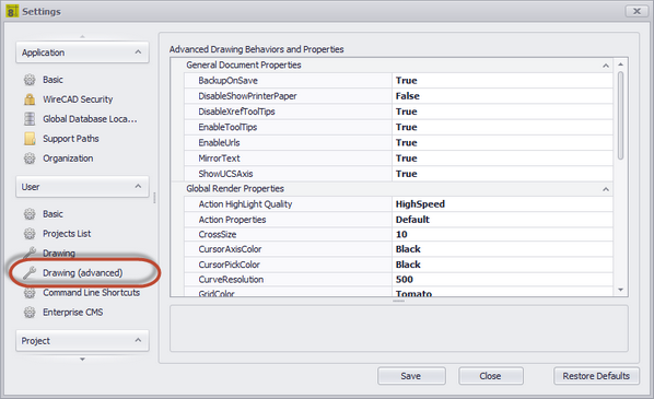
User - Drawing Advanced Panel Options
These are really granular controls of the render engine. It is beyond the scope of this manual to explain each we will hit some, but play with them if you are interested and see how they behave.
Item |
Description |
|---|---|
BackupOnSave |
Saves the file with the ~.bak extension before overwriting the existing file. |
DisableShowPrinterPaper |
Same as Show Paper Space Paper |
DisableXrefTooltips |
Sometimes XREF tooltips can be annoying. |
EnableTooltips |
Show tooltips or not. |
EnableURLs |
URLs of object will be opened. |
MirrorText |
Controls how the Mirror command deals with text. |
ShowUCSAxis |
|
|
|
ActionHighlightQuality |
Speed or Quality |
ActionProperties |
Default or HideOnLeave |
CrossSize |
|
CursorAxisColor |
|
CursorPickColor |
|
CurveResolution |
How many segments to a circle. |
GridColor |
|
LineDrawQualityMode |
Speed/Quality |
MappedImageBoundWidth |
Used only in 3D texture mapping. |
OSnapSize |
|
PickAdd |
Sets whether a user selection action replaces the current selection or adds to it. |
ReferenceCrossColor |
|
RenderingQuality |
Speed/Quality |
RubberBandColor |
|
SelectActionKey |
Set a key value used in combination with mouse-down to add or remove selected item(s) from a selection. |
SelectingCrossColor |
Crossing window select color. |
SelectingWindowColor |
Containing window select color. |
SelectionPreviewFlag |
Highlight entities that the mouse hovers over. |
ShowHatches |
Show hatches(filled objects). |
UseGLDIBBitmap |
|
|
|
Tooltip Fiddling |
Change the appearance and behaviour of the tooltips. |
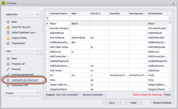
User - Command Line Shortcuts Panel Options
Item |
Description |
||||||||||||
|---|---|---|---|---|---|---|---|---|---|---|---|---|---|
Register Your Own Command |
Developer function |
||||||||||||
Remove Command |
Developer function |
||||||||||||
Check |
Checks the shortcuts to see if you have any duplicates. |
||||||||||||
Commands List |
You may freely edit any of the columns:
Even though the grid allows you to edit the following fields if you are not a developer you should NOT edit any of the columns:
You will break WireCAD. |
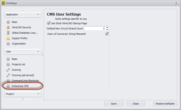
User - Enterprise CMS Panel Options
Item |
Description |
|---|---|
Use Stock WireCAD Startup Page |
This will change your Startup page from the CMS specific page to the default WireCAD page. |
Default New Circuit Strand Count |
When creating a new circuit, a default strand count for jumpers is created. This will change that strand count to a different value. |
Warn of Connector String Mismatch |
Having this box checked will allow a warning message to display anytime WireCAD detects that 2 ports being connected have a different connector type. |
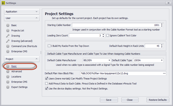
Item |
Description |
|---|---|
Starting Cable Number |
The default starting number of ALL sequences. |
Leading Zero Count |
How many leading zeros in SysNames and Cable Numbers |
Ignore Cable # Text Color |
Does not color the Cable Number text entities. |
I Build My Racks From the Top Down |
Probably should read I number my racks from the top down. |
Default Rack Height |
|
Default Cable Type |
This is the default of defaults. The Signal Types table can override this. |
Default Plan View Block File |
If no Plan View File is defined on the Equipment definition then this will be used by the Populate Equipment function in the Plan View Tools. |
Users (mere mortals) Can Modify These Project Settings |
If you can see and edit this you are a WireCAD Administrator or have not set up WireCAD Security. |
Add Pinout Data to Each Cable |
Allow pinout data to be attached to a cable as it is being assigned. The pinout criteria must match in order to be a candidate for inclusion in the list of available pinouts for a cable. |
Use the device display settings |
This setting prioritizes any Equipment Library device settings saved with the device over the settings saved for the project. |
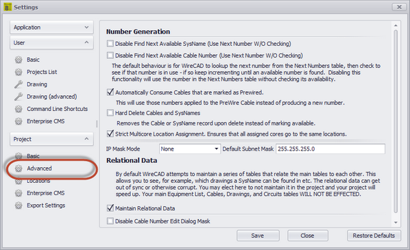
Project - Advanced Panel Options
Item |
Description |
|---|---|
Disable Find Next Available SysName |
The default behaviour is for WireCAD to lookup the next number from the Next Numbers table, then check to see if that number is in use - if so keep incrementing until an available number is found. Disabling this functionality will use the number in the Next Numbers table without checking its availability. |
Disable Find Next Available Cable Number |
|
Automatically Consume Prewire Cables |
This will use those numbers applied to the PreWire Cable instead of producing a new number. |
Hard Delete Cables and SysNames |
Overrides the default behaviour which is to mark a deleted cable Available=true and place Deleted in key fields. Enabled this removes the row from the table upon deletion. |
Strict Multi-core Assigment |
Enforces a policy that all cores in each end of a multi-core cable must originate from the same location. |
IP Mask |
|
Maintain Relational Data |
By default WireCAD attempts to maintain a series of tables that relate the main tables to each other. This allows you to see, for example, which drawings a SysName can be found in etc. The relational data can get out of sync or otherwise corrupt. You may elect here to not maintain it in the project and your project will speed up. Your main Equipment List, Cables, Drawings, and Circuits tables WILL NOT BE EFFECTED. |
Disable Cable Number Edit Dialog Mask |
If you find the masking of the Edit Cable Data Cable Number textbox to be cumbersome you can disable it here. |
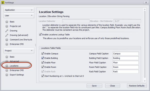
Project - Locations Panel Options
Item |
Description |
|---|---|
Location Delimiter |
Settable on project creation only this is the delimiter that separates CAMPUS from BUILDING, BUILDING from FLOOR, etc. The default is a [.]. This will create Qualified Locations in the form of: Campus.Building.Floor.Room.Rack |
Elevation-Slot Delimiter |
The delimiter that separates the elevation numeric from the slot numeric. For example: a device located in elevation 20 at slot 5 with a delimiter of a dash [-] would be typed and 20-5. |
Enable Locations Lookup |
If disabled the locations field may be typed into directly. This may lead to confusion or referencial issues, ie; user a calls something Rack 1 and user b calls the same thing RK 01. |
Locations Table Fields |
Enable those that you will use. |
Start Numbering at 1 |
Only applies if you are auto generating locations. |
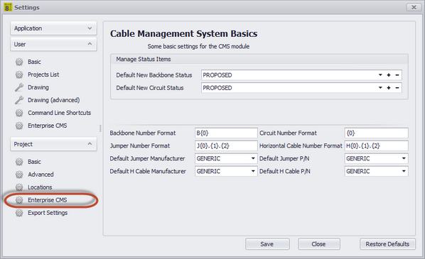
Project - Enterprise CMS Panel Options
Item |
Description |
|---|---|
Manage Status Items |
When creating a backbone, you have the ability to mark a "status" on that backbone such as "In Use", "Proposed" ETC. Using the [+] button, you can create new status items. Selecting a status will cause that to become the default for all backbones in this project. |
Backbone Number Format |
The variable {0} contains the next number in the Next Numbers grid for Backbones. Define the string format of the next Backbone number. |
Jumper Number Format |
The variable {0} contains the Circuit base number. The variable {1} contains the Strand Number of the circuit for this jumper The variable {2} contains the Ordinal Number of the circuit for this jumper. Define the string format of the next Jumper number. |
Default Jumper Manufacturer and P/N |
|
Default Horizontal Cable Manufacturer and P/N |
|
Circuit Number Format |
The variable {0} contains the next number in the Next Numbers grid for Circuits. Define the string format of the next Circuit number. |
Horizontal Cable Number Format |
The variable {0} contains the next number in the Next Numbers grid for Horizontal Cables. Define the string format of the next Horizontal Cable number. |
|
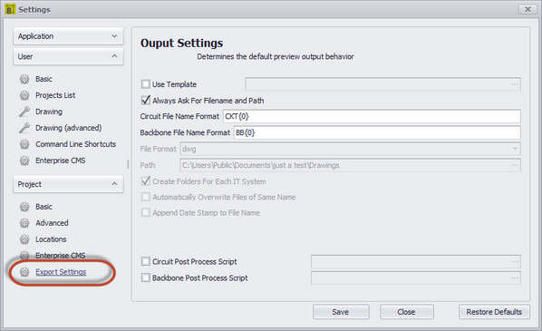
Project - Export Settings Panel Options
Item |
Description |
|---|---|
Use Template |
Path to to a template drawing that the output will be exported into. Your template drawings can contain any page borders or layouts and settings that you wish. |
Always Ask for FileName and Path |
You are involved in the filename selection and path |
Circuit FileName Format |
Sets the file name format for Circuit output. {0} = Circuit Name |
Backbone FileName Format |
Sets the file name format for Backbone output. {0} = Backbone Number |
File Format |
Presets the output format. |
Path |
Where do we output. |
Create Folder for Each IT Systems |
Create a new folder for each IT System and output the preview to that folder. |
Automatically Overwrite Files of Same Name |
Self-explanatory. |
Append Date Stamp to FileName |
|
Circuit Post Process Script |
Path to a c# file which will be run post export but pre write-to-disk. See the Post Process Scripts topic for more information. |
Backbone Post Process Script |
|
|