Navigation: CAD Basics > Drawing File Structure >
Model Space Boundaries


|
Navigation: CAD Basics > Drawing File Structure > Model Space Boundaries |
  
|
|
Model Space Boundaries ![]()
Default Keyboard Shortcut: None
Function:
Create a rectangle in the Model space that correlates to a scale factor and provides a drawing boundary.
Boundary Control Description
Item |
Description |
Layout combo |
Select the layout for which to create a boundary. |
Model Space Text Height |
Used to describe the smallest text height in the Model space. |
Final Output Text Height |
The desired final output text height. |
<OK> |
Create the boundary. |
<Cancel> |
Exit the command. |
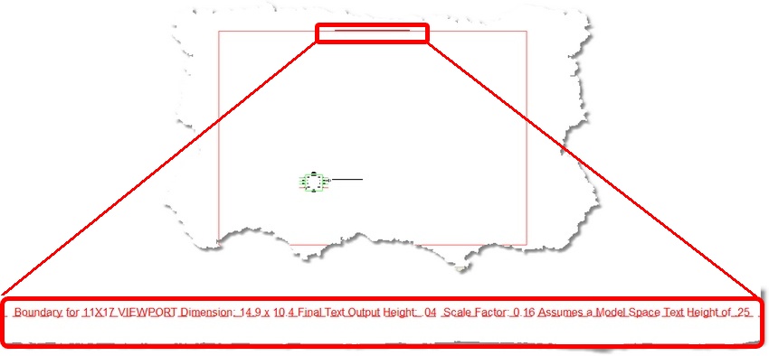
The Model Space Boundaries function takes two arguments, the Model Space Text Height and the desired Final Output Text Height. Using these two variables in conjunction with the size of the Viewports in the selected Layout to create a boundary rectangle in the Model space. Each boundary is accompanied by a text description that describes the Viewport to which the boundary applies, as well as the text heights and scale factor.

A boundary is created for each Viewport in the selected layout. A layer is created to contain the boundary for each layout. ![]() The default color for the boundary is grey.
The default color for the boundary is grey.
How To: Create and Use a Boundary
1. Determine the final output text height. You should determine this based on a number of factors, including: your printer or plotter's capability, the paper to which you are printing, the font you are using, and the age of the eyeballs that are going to be reading the text. We have found through our experience that about the minimum readable text height in inches is 0.04. You should test this for yourself using your printer or plotter and the font and paper that you are going to use.
2. Determine the height of the most common text height in the model space.
Note: The WireCAD default text height is 0.25 DU.
3. Launch the command by clicking on the ![]() .
.
4. Enter the required values and select a layout.
5. Click <OK>. The boundary or boundaries will be added to the model space.
6. Draw your drawing within the boundary.
7. Switch to a layout for which you have a boundary and activate the Viewport. For more on Viewports click here
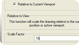
8. With the Viewport active, click the Zoom Scale function![]() (this button is disabled until a Viewport is activated). Enter the scale factor of the boundary in the Scale Factor textbox. Select the Relative to Current Viewport option. Click <OK>. The boundary will be scaled but not positioned.
(this button is disabled until a Viewport is activated). Enter the scale factor of the boundary in the Scale Factor textbox. Select the Relative to Current Viewport option. Click <OK>. The boundary will be scaled but not positioned.


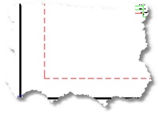
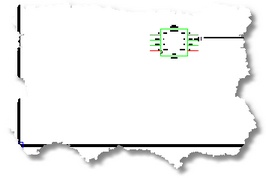
9. To position the boundary, pan the Viewport using the Mousewheel until the boundary disappears beneath the Viewport bounding box.

10. Deactivate the Viewport.
11. Done.