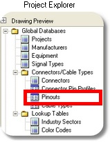
Navigation: WireCAD Databases > Global Databases > Connectors/Cable Types >
Pinouts


|
Navigation: WireCAD Databases > Global Databases > Connectors/Cable Types > Pinouts |
|
|
Pinouts
Menu: Databases>Connector / Cables>Pinouts
Default keyboard shortcut: None
Function:
WireCAD defines a Pinout as the conductor level data associated with a given cable. This includes the source and destination connector and the cable type. WireCAD maintains this information in data form and can present it either in data sheet view or as a drawing detail. See the details below.
Pinouts Designer Control Description
Item |
Description |
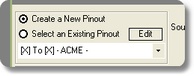
Create a New Pinout option |
Create a new Pinout. Activates most of the controls on this form. |
Select or Edit an Existing Pinout option and drop down |
Select a Pinout to display/Edit |
<Edit> |
Edit the data sheet view of the selected Pinout. |
Source Connector dropdown |
Select the left hand connector. |
Source Connector <+> |
Add a new connector |
Source Connector Pin Profile dropdown |
Select the left hand connector pin profile. |
Source Connector Pin Profile <+> |
Add an new connector pin profile. |
Source Connector Pin Profile <Load> |
Load the selected connector pin profile into the graphical drawing space. |
Destination Connector dropdown |
Select the right hand connector. |
Destination Connector <+> |
Add a new connector |
Destination Connector Pin Profile dropdown |
Select the right hand connector pin profile. |
Destination Connector Pin Profile <+> |
Add an new connector pin profile. |
Destination Connector Pin Profile <Load> |
Load the selected connector pin profile into the graphical drawing space. |
Cable Manufacturer dropdown |
Select the Cable Manufacturer. |
Part Number dropdown |
Select the Cable Type Part Number. |
Conductor grid |
Conductor list for the selected Cable Type Part Number. The selected conductor will be used with the Draw Conductors function. |
Drawing Space |
Graphical Pinout. |
<Draw Conductor> and Tools>Draw Conductor |
First you must select the conductor from the Conductors grid. Then draw from a pin on the left connector to a pin on the right connector. |
<Delete Conductor> and Tools>Delete Conductor |
Deletes the selected conductor. |
<Draw Jumper> and Tools>Draw Jumper |
Jumpers are drawn from one pin to another on the SAME connector. |
<Clear Conductors> and Tools>Clear Conductors |
Clear the conductors from the drawing. |
<Pin-for-Pin> and Tools>Pin-for-Pin |
Not yet activated |
<Save as Profile> and Tools>Save as Profile |
Save the graphical Pinout as a data view. |
<Cancel> and File>Cancel |
Exit |
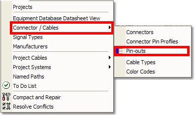
1. Start the command by clicking Databases>Connectors/Cables>Pinouts |
|
2. Click Create New option. |
|
3. Clear the drawing space if necessary by right-clicking and click Erase All. |
Note that this function simply clears the drawing space it does not delete the pinout data. |
4. Select the Cable Manufacturer. |
Add if not in the database. |
5. Select the Cable Part Number. |
Add if not in the database. |
6. Select the Source Connector and . |
Add if not in the database. |
7. Select the Source Connector Pin Profile. |
Add if not in the database. Click <Load> to add to the Drawing Space. |
8. Select the Destination Connector Pin Profile. |
Add if not in the database. Click <Load> to add to the Drawing Space. |
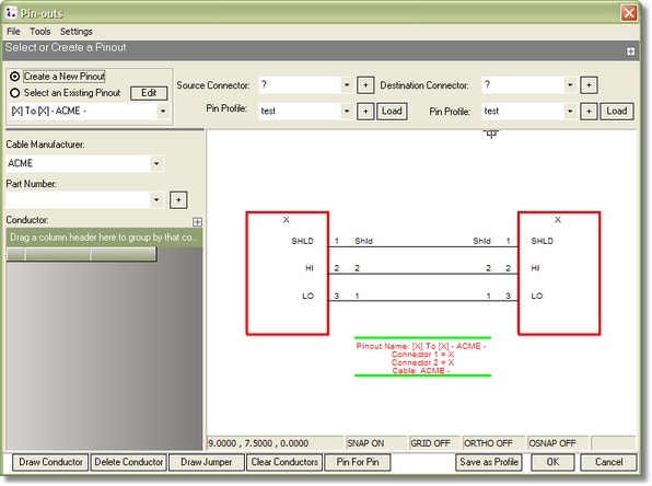
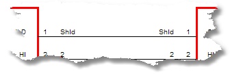
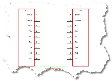
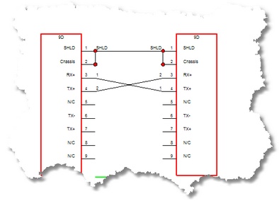
9. At this point you should have something that looks like this:
Note: your connectors may be different. |
|
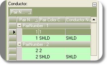
10. Select the Conductor from the Conductors grid. |
|
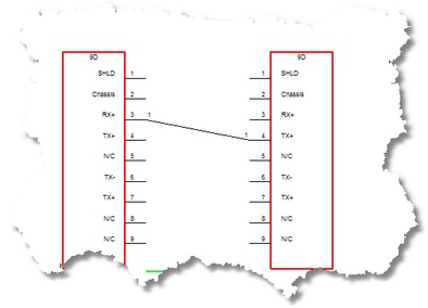
11. Click <Draw Conductor> and then select the pin on the Source Connector followed by the pin on the Destination Connector. |
|
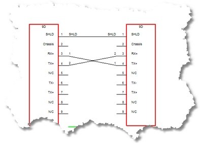
12. Lather, rinse, repeat. |
|
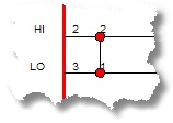
13. Add any jumpers by clicking <Draw Jumper>.
Note: jumpers are drawn on the same connector. |
|
14. Save the finished Pinout in data form by clicking <Save as Profile>. |
|
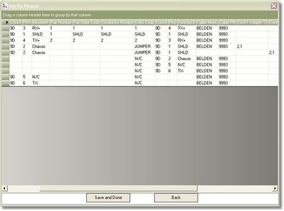
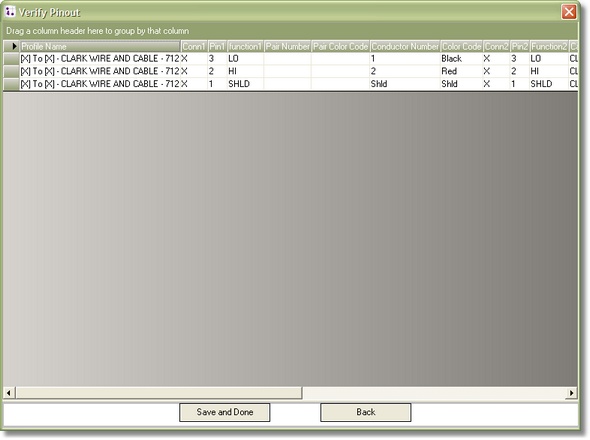
15. Edit the data and add any Termination Method data or notes. |
|
16. Click <Save and Done>. |
|
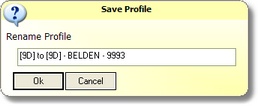 The default profile name.