Navigation: CAD Basics > Drawing File Structure >
Layers


|
Navigation: CAD Basics > Drawing File Structure > Layers |
|
|
Layers ![]()
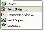
Menu: Format>Layers...
Default Keyboard Shortcut: SL
Function:
Layer is the equivalent of the overlay used in paper-based drafting. It is the primary organizational tool in WireCAD, and you can use it to group information by function and to enforce linetype, color, and other standards.
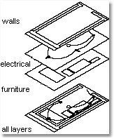
Organizing Layers and the objects on Layers make it easier to manage the information in your drawings. When you put one layer over another then the result is the complete drawing.
There is no limit to the number of layers you can place in a drawing.
When you begin a new drawing, WireCAD creates a special layer named 0. By default, layer 0 is assigned color number 7 (white or black depending upon your background color), the CONTINUOUS linetype and a lineweight of Default (the default setting is .01 inch or .25 mm). Layer 0 cannot be deleted or renamed.
All new objects are added to the active layer if no layer is specified.
|
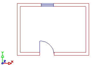
By controlling whether a Layer's state is Thaw or Frozen you can change the appearance of your drawing to display only the information on the Layers that are visible. Freezing unused Layers will help the performance of WireCAD |
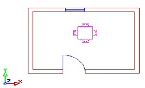
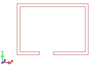
In the drawing below (Picture 1) there are 3 types of items: walls (the lines and Polylines with red color), doors&windows (Blue color) and furniture (Magenta).
These objects are teamed and drawn in different layers. Walls placed on layer "WALLS", Doors&windows are placed on layer "WIN_DOORS" and furniture are placed on layer "FURNITURE".
Picture 1 |
|
Picture 2 |
|
Picture 3 |
|
WireCAD Specific Layers
WireCAD requires a specific set of layers in order to operate properly. These layers are added automatically if you open a drawing file in WireCAD. A list of the necessary layers is available in the appendix. WireCAD will also create a series of layers for each signal type that is added to the drawing. As Follows:
Drawing Entity |
Layer Name |
Cable Polyline |
= SignalType |
Cable Number Text |
= SignalType_No |
Block Pin |
= SignalType_Pin |
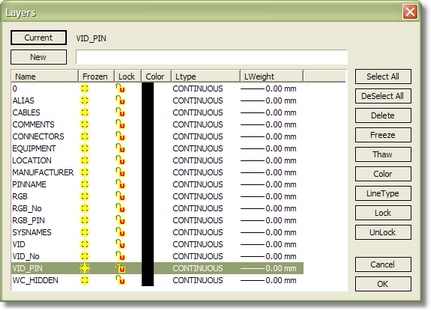
Layer Dialog Button Functions
Item |
Description |
<Select All> |
Selects all layers for use with buttons below. |
<DeSelect All> |
De selects selected layers. |
<Delete> |
Deletes selected layer(s). |
<Freeze> |
Freezes or hides the selected layer(s). |
<Thaw> |
Thaws or shows the selected layer(s). |
<Color> |
Changes the color associated with the layer(s). Entities in the drawing that have their PenColor set to ByLayer will inherit the layer color. |
<LineType> |
Changes the line type associated with the layer(s). Entities in the drawing that have their Line Type set to ByLayer will inherit the layer LineType. |
<Lock> |
Locks the selected layer(s). Items on locked Thawed layers are visible though they cannot be selected. |
<UnLock> |
Unlocks the selected layer. |
![]() Create a new layer based on the name entered in the textbox.
Create a new layer based on the name entered in the textbox.
![]() Sets the current layer.
Sets the current layer.
Please Note: WireCAD will not allow the current layer to be frozen.
How To: Add a New Layer
| 1. | Click Format>Layers... |
| 2. | Enter the name for the new layer in the textbox. It is recommended that you not use spaces or special characters. |
| 3. | Click <New>. The layer will be added. To make the new layer the current layer. Select the layer in the list and click <Current>. |