
Things to Think About When Starting
I get these questions routinely:
There don't seem to be any standards, so how do I put together a set of drawings to lay out my design?
How do I structure my drawings?
Should I show my Video signals separate from my audio?
Should I draw everything in one big drawing or use many smaller drawings?
Should I put the router in one drawing or just show the router crosspoints that feed devices?
Should I draw all of the systems in a given rack together?
Ah philosophy....
And now a flashback to your creative writing class.
I find that it helps to define your audience and work based on that.
Let us assume that you are creating a set of documents for your brand shiny new facility.
Some of the potential audiences for these documents are: the management, the technical staff, the installation crew.
It is possible that you could create a single document to serve all the audiences, but not likely.
That is what we call a moo-moo drawing. One-size-fits-all, but not always appealing.
The management will say that the drawing is too busy, the installers will say that the drawing is too sparse, and the technical staff will say that they can't find anything.
So let's break this down by audience and discuss how WireCAD might or might not serve this audience.
Drawings for Management
The management will probably need high level overview drawings that are not too detailed. These documents typically have an emphasis on "pretty pictures" over "detail".
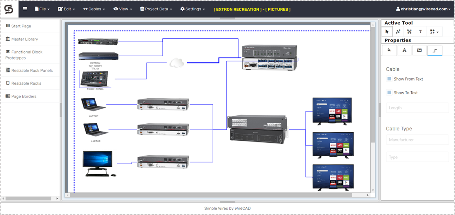
While you can use WireCAD for this type of drawing, there are many better pictographically oriented drawing tools out there.
Drawings for Troubleshooters
This audience for our design is typically concerned with two types of drawings:
1. Overview - the management drawings may fill this need, if not, you may need to create a set of top level drawings.
2. Systems, or sub-system views.
For your system views, you will want to think like a troubleshooter. What do they need to see in the event of a system failure.
If the system is complex, you may want to separate the audio signals from the video, but you may find that it is better to draw key signal flows.
If you are designing a TV or radio station, you may want to show the entire air-chain to your troubleshooter.
If you are designing a production facility, you may want to separate the studios from the production control rooms.
I find it helpful to centralize the distributed systems like:
1. Network
2. Reference distribution
3. Routing / Patching
4. KVM
5. Multiviewers
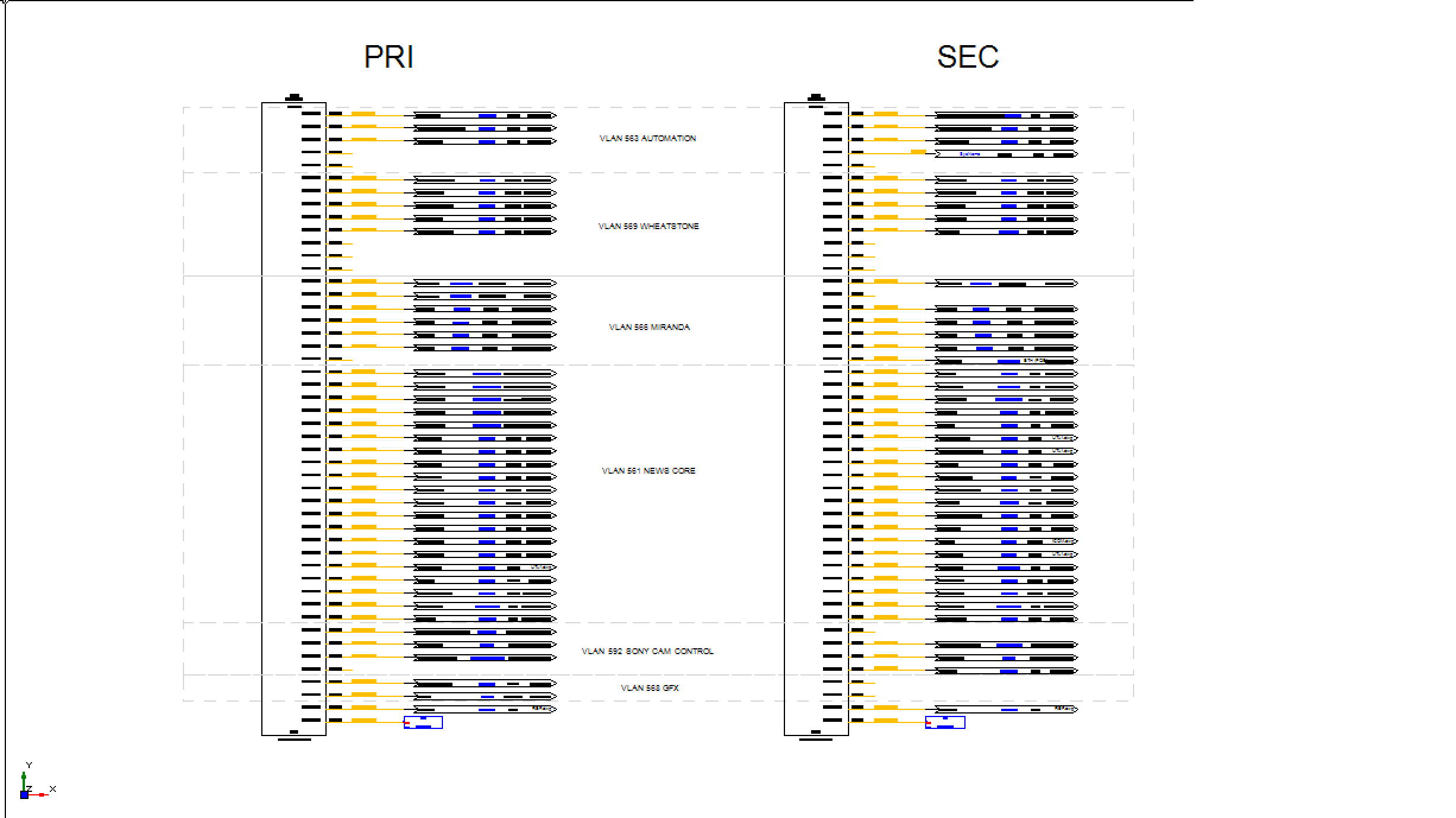
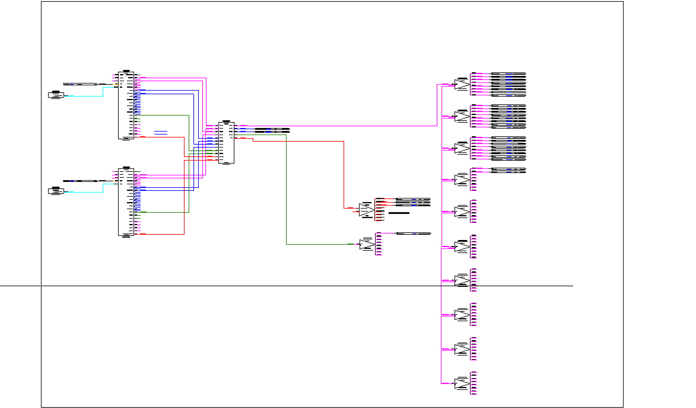
Then, thinking like a troubleshooter, I will create signal flow documents for each of the spaces that the central systems touch.
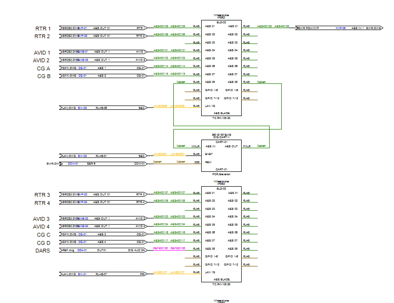
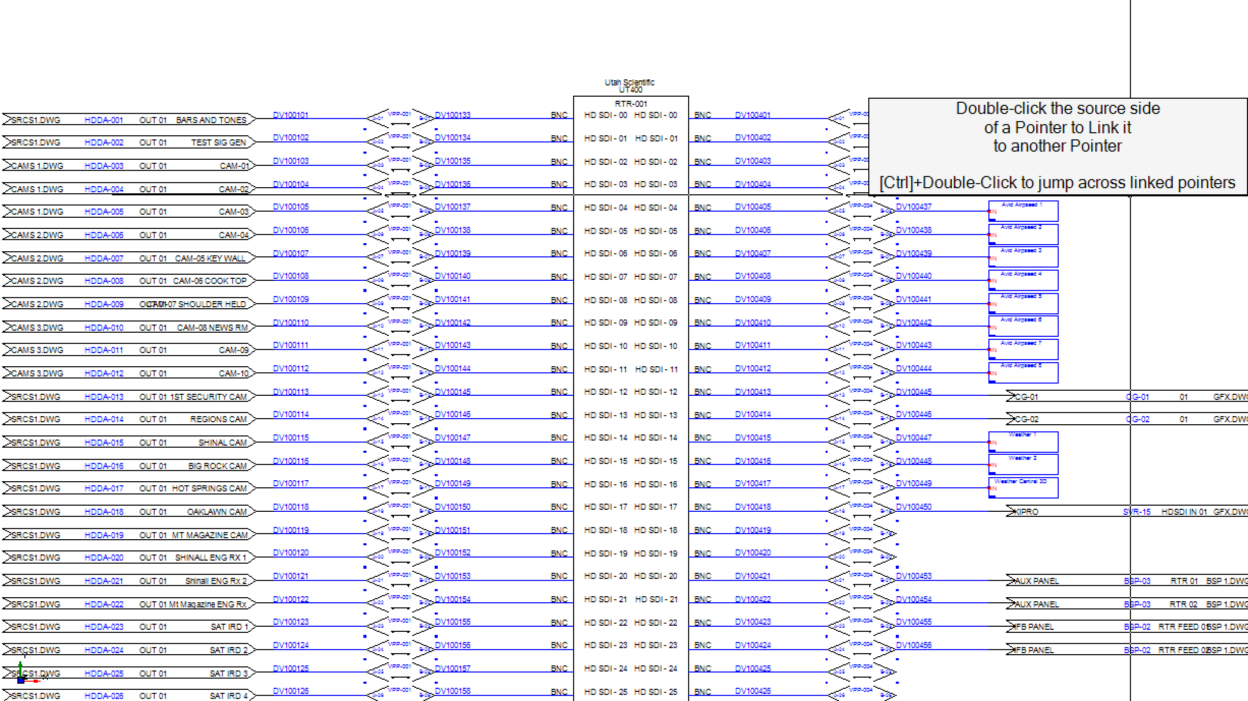
As you can see from the examples above, I have made extensive use of off-sheet pointers in order to centralize my distributed systems.
There are those that would argue that the use of offsheet pointers slows down the troubleshooter, and they are not wrong if the troubleshooter is looking at paper. However, if the troubleshooter is working in WireCAD or the WireCAD Teams Portal, they can simply double-click to follow the pointer.
Drawings for Installers
I will centralize the distributed systems as in the example above. Instead of creating a lot of smaller subsystem, or signal-based drawings, I use a drawing-per-rack, drawing-per-row, or drawing-per-room approach.
If we are talking philosophy, I don't necessarily create drawings for installers. I create drawings to create data for installers. There are obviously exclusions to this rule like floor plans, elevations, reflected ceiling plans, and panel layout drawings.
I don't want my installers installing to a system drawing. It is difficult to audit the progress on a drawing. I want my installers to install to my lists. I provide a package to the installation crew that includes the drawings, equipment lists (with mounting locations), cable pull schedules (cable type, count, location-to-location), cable run sheets and cable labels.
By taking this approach I can easily audit a list for completion.
My cable lists include check boxes for:
1. Cable Pulled
2. Terminated
3. Labeled
4. Landed
5. Tested
As you can see, by taking this approach it is very easy to understand the installation status of a project.
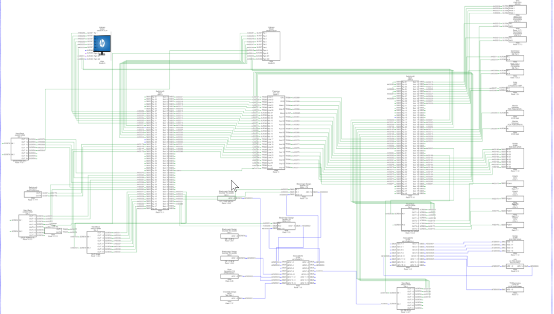
When I am creating this type of drawing I will put as much stuff on a page as I can possibly fit.
This approach creates a very busy, but accurate, drawing that the installers can reference; and that provides the needed data to the database.
I recommend taking the time to create a style guide. This will help answer the easy questions and provide a framework for working through the harder questions and outlying use cases.
If you don't already have a style guide you can download our free starter guide here:
https://www.wirecad.com/downloads/styleguide/DesignStyleGuideTemplate.docx