Description
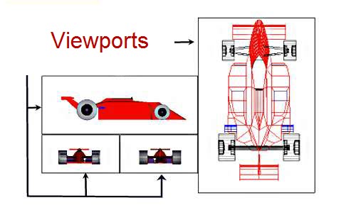
Viewports are areas that display different views of your model. As you work, you can split the drawing area into one or more adjacent rectangular views known as model viewports. In large or complex drawings, displaying different views reduces the time needed to zoom or pan in a single view. Also, errors you might miss in one view may be apparent into others.
ViewPorts are treated as rectangle drawing objects which display views and can be moved or resized.
They can be created only in entity list collection of a layout and not in Model.
With WireCAD 6.1 you can now attach viewports to closed polygons (polylines, circles, ellipses, rectangles).

Remarks
Those rectangles filled with the image of the model space objects in different scales depend from the ViewSize and the ViewCenter property. This way in one paper you can print out diffent views (with differnt scales) of the same drawing (Model Space) or parts of this drawing.
In viewports commands like Pan, Zoom and View3D of vdCommandAction objects can be applied, only when Viewport is Active (See ActiveViewport property of Layout object) and SpaceMode property of vdLayout has the value SPACEMODE_MODEL.