|
Model Space Boundaries |
  
|
|
Model Space Boundaries |
|
It's a big model space in there. We can, if we are not careful, create a drawing that is so big that it can't be effectively printed or plotted. In order to have some Idea of where the fences are WireCAD can place boundaries in the model space. The boundary is created from the viewport. We use the text height as the terms for our equation. We do this because a drawing is considered readable if we can read the text. If we can't read the text the drawing becomes useless.
In the following example we have created a viewport in our ANSI_A layout that is attached to a closed polyline. The polyline traces the page border that encroaches on the display space. We then create a boundary with our parameters. The results look like this:
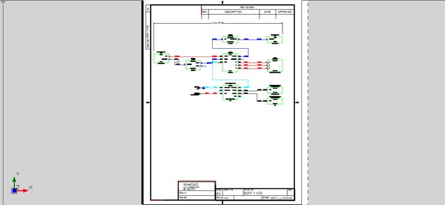
Layout with page border, and polygon viewport
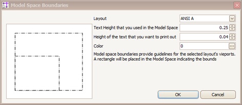
The Boundary dialog
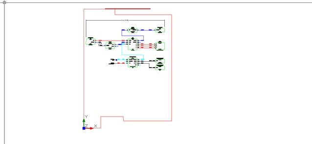
The boundary is created and positioned against the viewport from which it is created at the scale defined by our parameters