Navigation: CAD Basics > Tools >
Blocks, Inserts and Attributes


|
Navigation: CAD Basics > Tools > Blocks, Inserts and Attributes |
|
The .dwg file accommodates several complex or compound entities. We have already discussed several: rectangles (explode to Polylines) and dimensions (explode to Polylines, blocks, and text).
In this chapter we will be discussing three additional complex entities:
Blocks
Blocks. Blocks are groups of entities that are named and stored in the Blocks table in the drawing file. Blocks can be saved with the file but do not have to appear in the drawing space. In order for a block to appear in the drawing it must be inserted.
Blocks may be written out of the drawing (creating a new drawing file) using the Write Block function![]()
Blocks can also be inserted multiple times in the drawing.
Other drawings may be inserted into the current drawing. 
Other drawings may be externally referenced (Xref) ![]() or linked to the current drawing. This allows the drawing to be maintained elsewhere and updated remotely. The changes can then be updated in the current drawing.
or linked to the current drawing. This allows the drawing to be maintained elsewhere and updated remotely. The changes can then be updated in the current drawing.
Inserts
Inserts are instances of blocks that have been placed in the drawing. A Single block can have an unlimited number of inserts.
Attributes. Attributes are a special type of text entity that behave very differently from standard text. Attributes are meant to be used in blocks. Attributes will behave differently and display differently prior to being blocked.
An insert is a single instance of a block. A single block definition may have multiple inserts within the drawing. Take, for example, the case of a door block. The block is comprised of a straight line and an arc. These entities are grouped together and a base point is defined at the hinge point using the Tools>Insert>Create Block. Once the door block is defined, inserts of the block will be placed throughout the drawing as needed. This saves you the tedious task of recreating the door entities every time a door is needed.
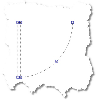 This door is comprised of an arc and a closed Polyline.
 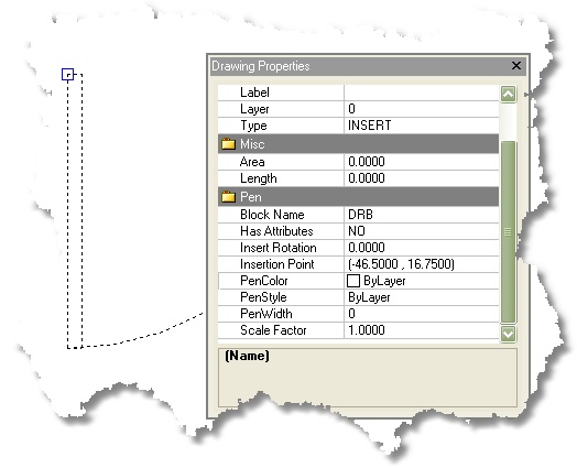 The entities are blocked together using the Tools>Inserts>Create Block function. A basepoint at is selected at the hinge point and the block is named DRB.
 DRB inserted and rotated.
Attributes
Text Versus Attributes
A block may contain Text entities, as well as a special type of text entity called an Attribute. Attributes are unique in that they may contain insert specific information. Attributes maintain data in TAG/VALUE pairs. The tag is used to identify the data contained in the value.
Attributes may be defined as visible or invisible.
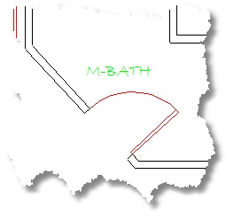
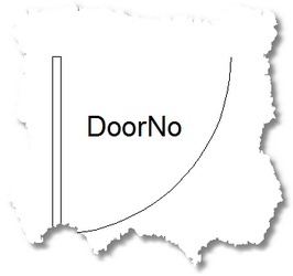
To use our door block example from above. Say we define an Attribute ![]() to group along with the line and arc. We designate the TAG as DoorNo for door number and we enter #### in the value field, and we set the visible value to true in order to display the attribute value upon block insertion. We then create our new door block and insert an instance of it in our drawing.
to group along with the line and arc. We designate the TAG as DoorNo for door number and we enter #### in the value field, and we set the visible value to true in order to display the attribute value upon block insertion. We then create our new door block and insert an instance of it in our drawing.
|
Attribute definitions will display the Tag string before inclusion in a block and the Value string after. As seen above the Tag string for this Attribute will be DoorNo. |

Our new block inserted
The real power of attributes now become apparent when we see that each insert can have its own attribute values.
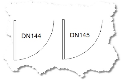
Two inserts of our new block - each with its own door number.
